- 您现在的位置:买卖IC网 > Sheet目录883 > SQE48T50012-NDA0 (Power-One)DC/DC EIGHTH BRICK
�� �
�
�SQE48T50012� DC-DC� Converter�
�36-75� VDC� Input;� 1.2� VDC� @� 50� A� Output�
�Data� Sheet�
�Operations�
�Input� and� Output� Impedance�
�These� power� converters� have� been� designed� to� be�
�stable� with� no� external� capacitors� when� used� in� low�
�inductance� input� and� output� circuits.�
�However,� in� some� applications,� the� inductance�
�associated� with� the� distribution� from� the� power�
�source� to� the� input� of� the� converter� can� affect� the�
�stability� of� the� converter.� A� 33� μF� electrolytic�
�capacitor� with� an� ESR� <� 1� ?� across� the� input� is�
�on� the� signal� polarity.� See� the� Startup� Information�
�section� for� system� timing� waveforms� associated� with�
�use� of� the� ON/OFF� pin.�
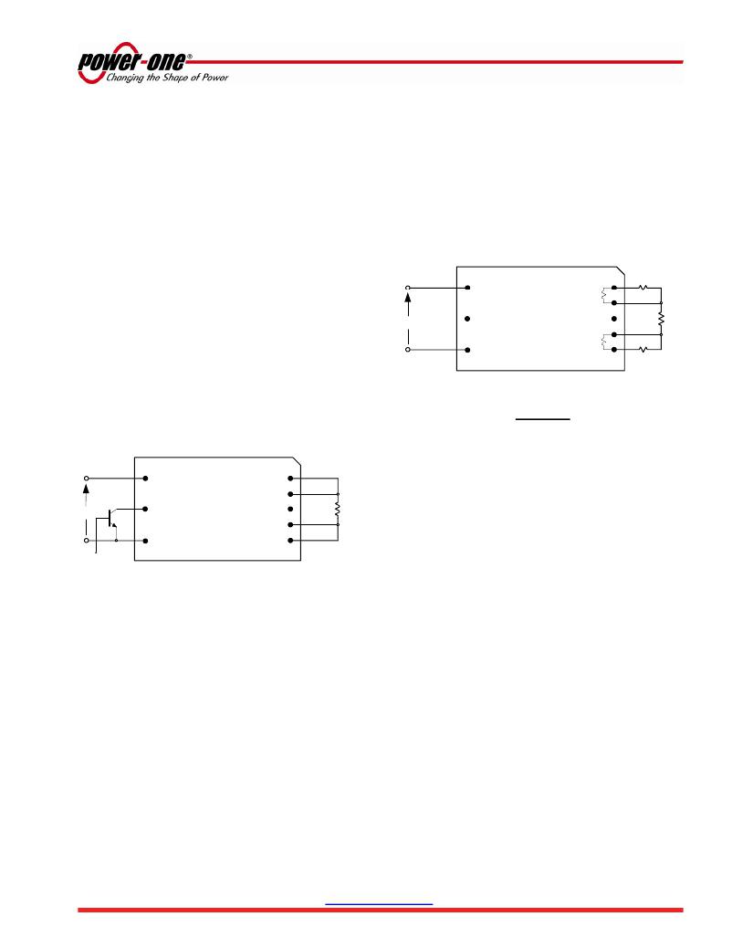
�Remote� Sense� (Pins� 5� and� 7)�
�The� remote� sense� feature� of� the� converter�
�compensates� for� voltage� drops� occurring� between�
�the� output� pins� of� the� converter� and� the� load.� The�
�SENSE(-)� (Pin� 5)� and� SENSE(+)� (Pin� 7)� pins� should�
�be� connected� at� the� load� or� at� the� point� where�
�regulation� is� required� (see� Fig.� B).�
�recommended� to� ensure� stability� of� the� converter.�
�In� many� applications,� the� user� has� to� use� decoupling�
�capacitance� at� the� load.� The� power� converter� will�
�exhibit� stable� operation� with� external� load�
�capacitance� up� to� 20,000� μF.�
�ON/OFF� (Pin� 2)�
�Vin�
�Vin� (+)�
�ON/OFF�
�Vin� (-)�
�SQE48� Converter�
�Vout� (+)�
�(Top� View)� 100�
�SENSE� (+)�
�TRIM�
�SENSE� (-)�
�10�
�Vout� (-)�
�Rw�
�Rw�
�Rload�
�The� ON/OFF� pin� is� used� to� turn� the� power� converter�
�on� or� off� remotely� via� a� system� signal.� There� are� two�
�remote� control� options� available,� positive� and�
�negative� logic,� with� both� referenced� to� Vin(-).� A�
�typical� connection� is� shown� in� Fig.� A.�
�Fig.� B:� Remote� sense� circuit� configuration.�
�CAUTION�
�If� remote� sensing� is� not� utilized,� the� SENSE(-)� pin� must� be�
�connected� to� the� Vout(-)� pin� (Pin� 4),� and� the� SENSE(+)� pin�
�must� be� connected� to� the� Vout(+)� pin� (Pin� 8)� to� ensure� the�
�converter� will� regulate� at� the� specified� output� voltage.� If� these�
�Vin� (+)�
�SQE48� Converter�
�(Top� View)�
�Vout� (+)�
�SENSE� (+)�
�connections� are� not� made,� the� converter� will� deliver� an�
�output� voltage� that� is� higher� than� the� specified� data� sheet�
�value.�
�Vin�
�ON/OFF�
�TRIM�
�Rload�
�Because� the� sense� leads� carry� minimal� current,�
�SENSE� (-)�
�large� traces� on� the� end-user� board� are� not� required.�
�CONTROL�
�INPUT�
�Vin� (-)�
�Vout� (-)�
�However,� sense� traces� should� be� run� side� by� side�
�and� located� close� to� a� ground� plane� to� minimize�
�Fig.� A:� Circuit� configuration� for� ON/OFF� function.�
�The� positive� logic� version� turns� on� when� the� ON/OFF�
�pin� is� at� a� logic� high� and� turns� off� when� at� a� logic�
�low.� The� converter� is� on� when� the� ON/OFF� pin� is� left�
�open.� See� the� Electrical� Specifications� for� logic�
�high/low� definitions.�
�The� negative� logic� version� turns� on� when� the� pin� is�
�at� a� logic� low� and� turns� off� when� the� pin� is� at� a� logic�
�high.� The� ON/OFF� pin� can� be� hard� wired� directly� to�
�Vin(-)� to� enable� automatic� power� up� of� the� converter�
�without� the� need� of� an� external� control� signal.�
�The� ON/OFF� pin� is� internally� pulled� up� to� 5� V�
�through� a� resistor.� A� properly� de-bounced�
�mechanical� switch,� open-collector� transistor,� or� FET�
�can� be� used� to� drive� the� input� of� the� ON/OFF� pin.�
�The� device� must� be� capable� of� sinking� up� to� 0.2� mA�
�at� a� low� level� voltage� of� ≤� 0.8� V.� An� external� voltage�
�source� (±20� V� maximum)� may� be� connected� directly�
�to� the� ON/OFF� input,� in� which� case� it� must� be�
�capable� of� sourcing� or� sinking� up� to� 1� mA� depending�
�system� noise� and� ensure� optimum� performance.�
�The� converter’s� output� overvoltage� protection� (OVP)�
�senses� the� voltage� across� Vout(+)� and� Vout(-),� and�
�not� across� the� sense� lines,� so� the� resistance� (and�
�resulting� voltage� drop)� between� the� output� pins� of�
�the� converter� and� the� load� should� be� minimized� to�
�prevent� unwanted� triggering� of� the� OVP.�
�When� utilizing� the� remote� sense� feature,� care� must�
�be� taken� not� to� exceed� the� maximum� allowable�
�output� power� capability� of� the� converter,� which� is�
�equal� to� the� product� of� the� nominal� output� voltage�
�and� the� allowable� output� current� for� the� given�
�conditions.�
�When� using� remote� sense,� the� output� voltage� at� the�
�converter� can� be� increased� by� as� much� as� 10%�
�above� the� nominal� rating� in� order� to� maintain� the�
�required� voltage� across� the� load.� Therefore,� the�
�designer� must,� if� necessary,� decrease� the� maximum�
�current� (originally� obtained� from� the� derating� curves)�
�by� the� same� percentage� to� ensure� the� converter’s�
�ZD-01731� Rev� 2.0�
�www.power-one.com�
�Page� 5� of� 13�
�发布紧急采购,3分钟左右您将得到回复。
相关PDF资料
SQL48T20033-NDA0G
CONV DC-DC 3.3V 20A 1/8 BRICK
SQM48S20033-NS00
DC/DC EIGHTH BRICK
SQM48T20010-PCB0
DC/DC EIGHTH BRICK
SRBA-03A1A0G
CONV DC/DC .75-5V ADJ 3A SMD
SRBA-03E1A0G
CONV DC/DC 3A .75-5.0V SMD
SRBA-06A2A0G
CONV DC/DC .75-5.5V ADJ 6A SMD
SRBA-06F2A0G
CONV DC/DC .75-3.63VDC 6A OUTPUT
SRBC-10A2A0G
CONV DC/DC .75-5V ADJ 10A SMD
相关代理商/技术参数
SQE48T50012-NDA0G
功能描述:DC/DC转换器 1.2Vout 50A 1.2Vout 50A RoHS:否 制造商:Murata 产品: 输出功率: 输入电压范围:3.6 V to 5.5 V 输入电压(标称): 输出端数量:1 输出电压(通道 1):3.3 V 输出电流(通道 1):600 mA 输出电压(通道 2): 输出电流(通道 2): 安装风格:SMD/SMT 封装 / 箱体尺寸:
SQE5-P
制造商:Power-One 功能描述:
SQETHERNET
制造商:Intel 功能描述:
SQF620001
功能描述:OSC 156.25MHZ 3.3V HCSL SMD RoHS:是 类别:晶体和振荡器 >> 振荡器 系列:SaRonix-eCera™ SQ 标准包装:1 系列:VG-4512CA 类型:VCXO 频率:153.6MHz 功能:三态(输出启用) 输出:LVPECL 电源电压:3.3V 频率稳定性:- 工作温度:-40°C ~ 85°C 电流 - 电源(最大):60mA 额定值:- 安装类型:表面贴装 尺寸/尺寸:0.276" L x 0.197" W(7.00mm x 5.00mm) 高度:0.071"(1.80mm) 封装/外壳:6-SMD,无引线(DFN,LCC) 包装:Digi-Reel® 电流 - 电源(禁用)(最大):- 其它名称:SER3790DKR
SQF69216
制造商:Honeywell Sensing and Control 功能描述:Pressure Transducers
SQF71K0J1453
功能描述:金属膜电阻器 - 透孔 SQF7 1K0 5% 145C 3A (METAL FILM) RoHS:否 制造商:IRC 电阻:63.4 kOhms 容差:1 % 功率额定值:100 mW 电压额定值:200 V 温度系数:100 PPM / C 端接类型:Axial 工作温度范围: 尺寸:2.3 mm Dia. x 6.4 mm L 封装:Bulk
SQF-P10
制造商:ADVANTECH 制造商全称:Advantech Co., Ltd. 功能描述:Advantech Industrial CompactFlash
SQFP100
制造商:ROHM 制造商全称:Rohm 功能描述:LSI Assembly